VLink TIF
Introduction
This guide provides the basic outline of configurations required to use VLink to connect ADAM to SIP phone systems and provide intelligent control and status of phone lines.
Please refer to your phone system administrator or SIP phone service provider for configuration information needed to properly connect SIP lines from your VLink, and which may be required on the phone system side for proper interconnect.
Phone Switch SIP Line Planning
The first step in a successful setup is to establish the number of phone lines to be configured and determine the details of the phone switch or SIP service provider being used. VLink will generally interface with any typical phone switch or service provider.
In each case there will be an IP address for the SIP line services, and most likely user name and password access information for each line being configured.
Before moving forward, please ensure this preliminary information is on hand for entry into the configuration screens described in this document.
Phone Switch / PBX Connect Method
There are two possibilities for the VLink TIF server to connect to a Phone Switch or PBX. The first is via a Registered connection where we use a username and password to register a SIP Client to the PBX and then receive and initiate calls via SIP Invites from/to the PBX in the same manner as a SIP client. The second is via a Direct IP or non-registered connection in which we only use the user name to receive and initiate calls via the PBX. In this case there is no registration or authentication but rather simply SIP Invites from/to the PBX. At some customer installations, this second method is used to install a SIP Trunk between the VLink TIF server and an offsite 3rd party provider for the phone line access.
IP Network Considerations
A critical element in successful planning is the IP network connectivity required for the system components to link to each other. Whether the SIP lines are provided by an external SIP service provider, or internal phone switch, the VLink server must have direct IP connectivity with at minimum TCP/UDP Port 5060 open between the VLink and the SIP signaling server. Also, all UDP ports must be open between VLink and the RTP media servers.
Additionally, the RTS ADAM Omneo card(s) and master controller cards, AZEDIT configuration PC, and optional Pacific Interactive TIF Tally display must have IP connectivity between each other and the server.
An important note about Dante audio is that it requires direct IP connectivity on the same local subnet. For this reason, the VLink server and the RTS Omneo cards should be plugged directly into the same network switch for best results. Other components can be plugged in anywhere on a network, so long as IP connectivity between them is available. If network connections between components other than the VLink server and Omneo card(s) are routed and/or protected by firewalls, certain TCP and UDP ports must be configured as passable between components.
Dante Virtual Soundcard (DVS)
This guide details audio connectivity between the VLink and RTS intercom utilizing Audinate’s Dante audio protocol. Instructions on how to install and activate DVS can be found on Audinate's website.
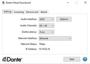
Once activated, select configure Dante's settings as shown above.
Audio Interface = ASIO Audio Channel = 64 x 64 Dante Latency = 4ms Network Interface = (choose the appropriate Ethernet connection the server uses)
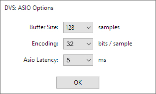
Next, click the options button and configure the fields as shown.
Buffer size = 128 samples Encoding = 32 bits / sample Asio Latency = 5 ms
RTS Intercom Port Planning
Based on the number of lines being interfaced, and the number of channels on the RTS OMNEO card, it is important at an early stage to clearly identify which phone line will connect to which intercom port. For example, if a 16 channel Omneo card is used, and it is installed as intercom ports 97-112, and the phone numbers being interfaced are 999-999-1001 thru 999-999-1016, you should determine and note which line will be on which RTS ADAM port. For this example, 999-999- 1001 might connect to intercom port 97, 999-999-1002 to port 98 thru 999-999-1016 connecting to intercom port 112.
Also note that VLink TIF server features require ADAM Master Controller software version 3.1.0 or later (3.4.1 or later preferred), and AZEDIT version 4.7.0 or later (5.1.0 or later preferred). Contact your RTS support representative should you require this software or assistance with upgrades.
VLink Configuration
To follow this portion of the guide your VLink server must be license. Follow the Licensing documentation to complete this step.
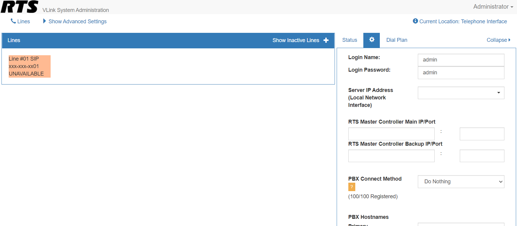
Next, set up the main system settings for SIP and the connection to the RTS ADAM intercom. Click on the System Settings button from the main System Administration window.
Server IP address (Local Network Interface) should be the IP address of this VLink under most circumstances.
RTS Master Controller Main / Backup IP should be the IP address of the ADAM main master controller followed by the IP address of the ADAM backup master controller.
RTS Master Controller Main / Backup IP Port should be 27415 / 27415 under most circumstances.
Adding a SIP Phone Line to VLink
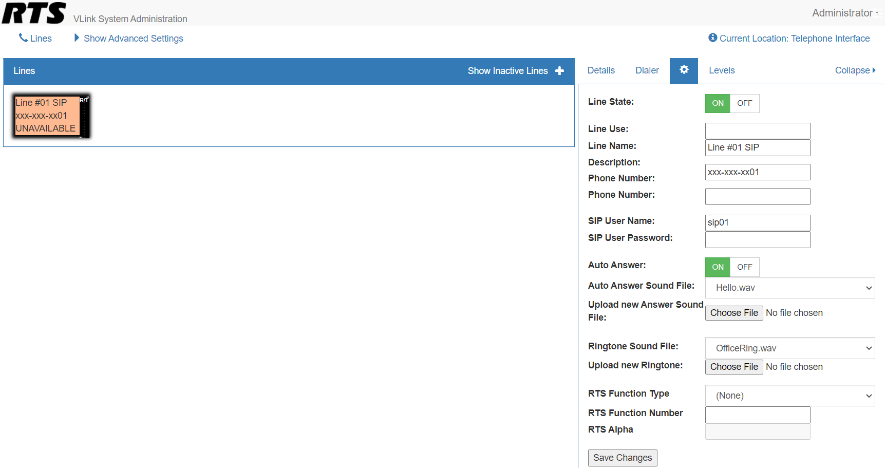
To add a SIP Phone line connection from your phone switch or service provider to the server click Show Inactive Lines from the main System Administration Window. From the lines list, select a line and click the settings gear button.
In the Line Name section enter the phone number. The Phone Number Section will be the name that will appear on the VLink Control Panel selector. Enter the Sip User Name and SIP User Password.
Important Notes
The SIP User Name and Password should be that provided by your SIP phone line
provider for that particular line. Click OK.
The Line Name field will be the one that is used and displayed within AZEDIT to link the VLink SIP line and the ADAM intercom ports, so it is highly recommended that the actual phone number is used for the Client Description. The Phone Number will be the default that is displayed on the optional Pacific Interactive Status Display System, however you will also be able to explicitly assign the specific ADAM type and function number (ie. IFB, # 1) as the alpha that will be displayed on a line-by-line basis.
Internal server Dante Virtual Soundcard Channel Connections
The connection between VLink and Dante Virtual Soundcard is done using the VLink Device Interface application. VLink Device Interface can be downloaded from our downloads page. After installing VLink Device Interface, a registry edit file is used to quickly configure it for use with VLink TIF.
The registry file can be downloaded here. Double-click the registry file. When prompted, click Run and then click Yes.
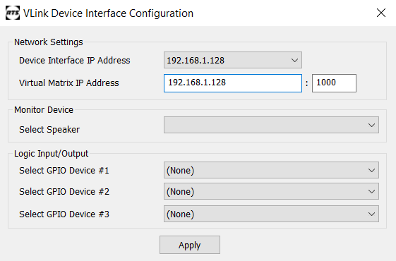
Launch VLink Device Interface. Enter in your VLink IP address in the Virtual Matrix IP Address field and click Apply.
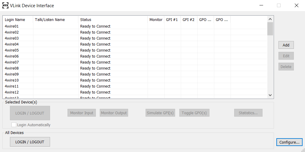
Each row in the VLink Device Interface represents a Dante connection to VLink. Click on a row and press the LOGIN button to connect to the VLink Virtual Matrix.
Setup of Audio Channels Between VLink and Omneo Cards
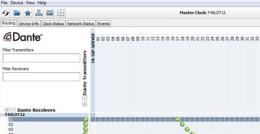
Once the SIP phone line has been configured to connect to VLink, and internally the server has been configured to send audio from an installed Dante Virtual Soundcard, the next step in configuration is to map audio channels from the Dante Virtual Soundcard to the associated ADAM Omneo channels. Note it is important to pre-design which phone lines will connect to which intercom port, as this mapping relationship will also need to be done later for phone line control.
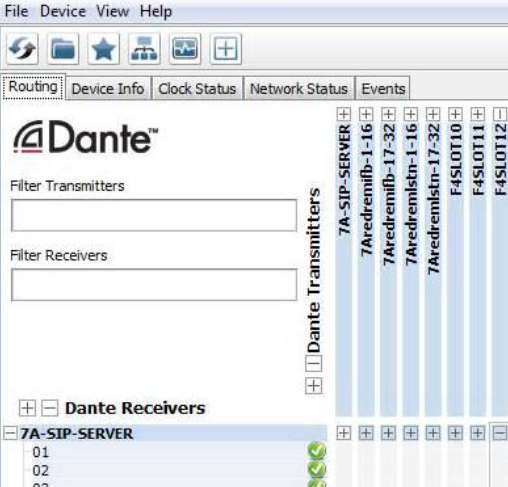
The screenshots above show a one-for-one mapping of phone lines in the server to intercom ports via Omneo in the intercom using the Dante Controller software
Click the + next to the VLink name on the left. Click the + next to the RTS Omneo Card name on the top. Click at the crosshairs to create an audio connection (indicated by a green circle) in a diagonal so each VLink channel is mapped in one direction to the associated Omneo card channel. Click the – next to the VLink Sever PC name on the left. Click the – next to the RTS Omeno Card name at the top.
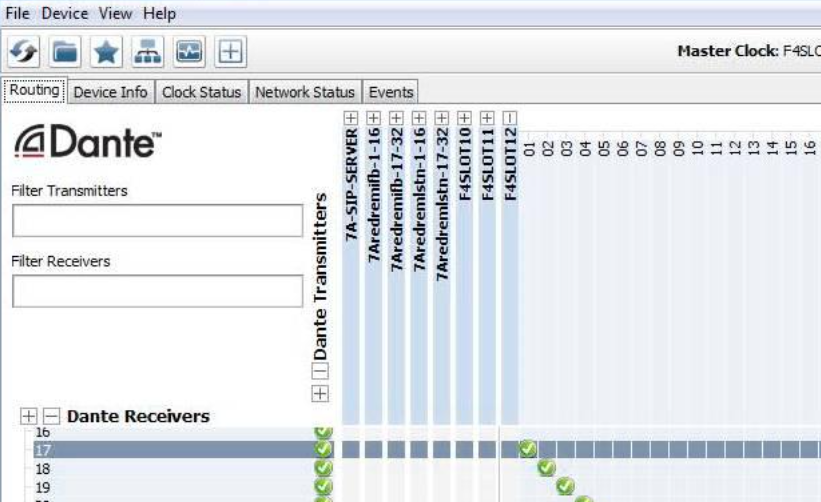
Next, click the + next to the RTS Omneo Card name on the left. Click the + next to the VLink name on the top. Click at the crosshairs to create an audio connection (indicated by a green circle) in a diagonal so each Omneo card channel channel is mapped in the other direction to the associated VLink channel.
Click the – next to the VLink Sever PC name on the left. Click the – next to the RTS Omeno Card name at the top.
To connect a VLink to be used for SIP phone line connection to an ADAM intercom, follow the steps below:
The RTS ADAM intercoms support up to eight redundant and separate SIP servers. In AZEDIT, name the server you are currently configuring. Click Alphas / SIP server. Double Click on the SIP server being configured.
Enter the SIP server Description in the EDIT box and click DONE.
Under Options/SIP server communications, enter the IP address of the SIP server (and redundant server if applicable) as shown below.
Intercom Port to SIP Line Association
Next you must tell the intercom which intercom port is connected via audio to which VLink device interface channel / SIP Phone Line. This must be consistent with how you have designed the phone line connection to the server 4-wire, and the internal Dante Virtual Soundcard channel to the Omneo intercom port channel.
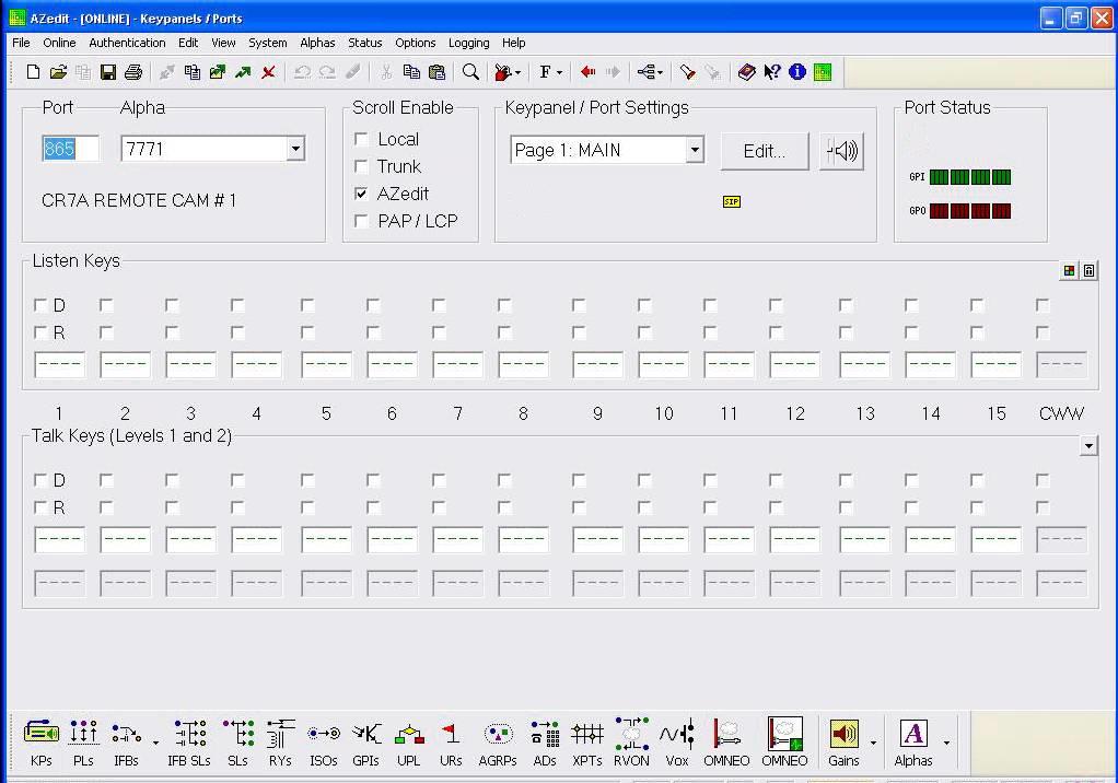
When completed, the intercom port keypanel setup page for each phone line’s intercom port will have a yellow SIP indicator box under the Edit button. From the keypanel setup screen for the first SIP phone line port, Click the EDIT button.
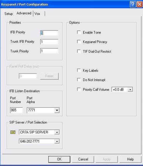
Click the Advanced Tab
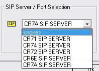
Under the SIP / server / Port Selection, Click the first pulldown and select the VLink for the phone lines being configured
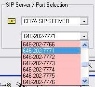
Click the second pulldown and select the VLink phone line to be associated with this RTS intercom port.
Click OK. Do this for each intercom port that has been connected to each of the VLink SIP phone lines
Testing
To test the completed system, first make sure all systems are turned on and connected to the IP network. Make sure the VLink Device Interface application is running. Additionally, make sure Dante Virtual Soundcard application is running (the Dante Controller Program does not need to be running).
Begin testing by opening a command prompt on the VLink server. One-by-one ping the IP addresses for the following and make sure a reply is received: IP address of phone switch or SIP service provider network, optional TIF Tally Display PC, RTS ADAM Primary master controller card, RTS ADAM back-up master controller card, RTS Dante Omneo card. If any of the devices are not pingable, check the IP network configurations and connections.
On the VLink server, using the System Administration program, click client statistics. Make sure the SIP line clients are shown as online. If not, check the configured SIP Provider / Phone switch settings and SIP login information for each line.
Also on the VLink server, maximize the Device Interface program which is running. Make sure all of the device interfaces are shown as Connected. If not, click configure and check the IP address in both fields is the IP address of the VLink server.
If necessary, click EDIT for each of the device interfaces and check the Dante Virtual Soundcard channel mapping. WARNING: NEVER EXIT OR CLOSE THE VLink DEVICE INTERFACE PROGRAM. Always just minimize it when you are done looking at status.
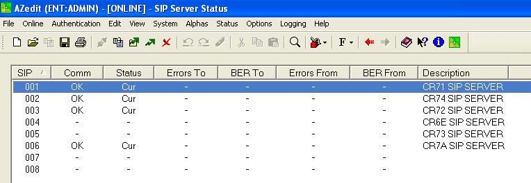
Check the SIP server status in AZEDIT.
When the VLink TIF server is correctly connected for SIP Line Control, you can see the status under Status/SIP server.
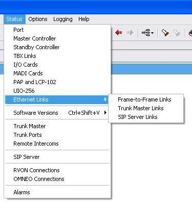
You can see more detailed status by going to Status/Ethernet Links/SIP server Links.
If status is not shown correctly, check the IP address listed for the VLink TIF server and check the network connection between the VLink and the ADAM Master Controller again.
Place key assignments on any RTS panel for the ports used for the SIP phone lines. Dial into each line from an external phone and check the functionality of auto-answer, manual answer by keypanel, and audio in both directions
Further operational information concerning RTS ADAM control of telephone line interfaces, including those which come from a VLink server is detailed below.
The VLink SIP phone lines are operated from the intercom keypanels, and from the dial pad on the telephone at the remote end of the line. Any keypanel with a keypad may use the VLink SIP phone lines. All that is necessary is to program a key to talk to the VLink SIP phone line, as if it were a keypanel. The alpha numeric display or tally LED for that key then provides information about the phone line. A solid display or non-illuminated LED indicates a line which is not in use. A slow flash indicates a line which is in use (off-hook). A rapidly flashing display or LED indicates a line which is ringing. In addition, the alpha numeric display shows digits as they are dialed, and the LED flashes for each digit.
NOTE: Displayed tallies are different if the Don’t Generate Tallies for TIF or Trunk Use option has been selected in Options|Intercom Configurations|Options.
To use a VLink SIP phone line, either to answer a call, or to call out, you first need to program a key to talk to the VLink SIP phone line. This is accomplished in the same manner as programming a key to talk to a keypanel. To program a key by port number, enter NUM-nnn_PGM-t, where NUM is the number 1 key, nnn is the port number of the TIF-4000 you want to use, and t is any talk key. You also need to use the listen key, so it should be assigned as either AF (auto-follow) or AL (auto-listen).
NOTE: The VLink SIP phone lines only respond to commands which are sent via a point-to-point key assignment. If you wish to use the VLink SIP phone line primarily on a PL, you must add a point-to-point assignment as the L2 talk assignment on the talk keys which are going to either answer the line, or dial out on the line.
Dialing a Call To dial a call on a VLink SIP phone line using a or KP-32, do the following: 1. Turn on the listen key for the line you wish to dial on. This allows you to hear dial tone, and your DTMF dialing tones. 2. Enter dial mode by entering PHONE-PGM-T. 21 PHONE is the 4 button on the keypad. PGM is on the keypad, and T is the talk key which is programmed to talk to the TIF-4000 you are dialing on. Leave the talk key in the latched position as you dial the number. 3. Dial the number. As you enter each digit, it appears in the alpha display above the key you are dialing on. If the listen key is latched, you hear each DTMF tone as it is generated. 4. When you have completed dialing, momentarily turn off the talk key to exit dial mode. The alpha numeric display reverts to normal, and you may use the key and keypad in the normal manner. NOTE: Digits 0-9 generate the DTMF digits 0-9. PGM generates the #, and CLR generate * (# and * are displayed for these keys). It is necessary to press CLR twice if you wish to generate an *, as a single CLR is used to trigger the speed dial and redial features.
To dial a call on a VLink SIP phone line using a KP-12 or KP-32, do the following: 1. Tap the phone key to begin your call. This places the keypanel in dial mode: the CALL indicator turns on, and the MAN DIAL (manual dial) displays in the call waiting window. You should also hear the dial tone. NOTE: You can hang up the phone line at this time by simply tapping the phone key again. 2. Tap SEL (select) to select MAN DIAL. The twelve intercom keys can now be used to dial a telephone number. Each key corresponds to the number printed next to it on the front of the panel. If the keypanel has alphanumeric displays, the key numbers are displayed above each key. 3. Begin dialing the number by tapping the appropriate keys. After you dial the first digit, END DIAL appears in the call waiting window. 4. When you have completed the dialing, tap SEL to select END DIAL. This returns the keypanel to normal operating mode. If the called party answers, proceed with your conversation.
Hanging Up
The VLink SIP line control detects the call at the far end has hung up under most
circumstances. It detects the hang up by either loop interrupt, battery reversal, or the presence of a
dial tone or busy signal. Some telephone systems do not provide any of the above, so it is
necessary to force a hang up. In addition, if the call was placed to an auto-answer device, it is
necessary to force a hang up when the call is complete.
Enter PHONE-CLR-t, where PHONE is the 4 on the keypad, CLR is the CLR button, and t is the talk key which is programmed to talk to the VLink SIP phone line which you want to hang up. This disconnects the line for which you struck the talk key. NOTE: If talk is in the on position, you must turn off the key, then momentarily turn it on again to indicate which line you wish to disconnect. If the line is in dialing mode, then you must first exit dialing mode by turning off the key, then use PHONE-CLR-t to hang up.